We own a BUVA Boxstream mechanical ventilation system in our home that i wanted to automate. There is a 0-10V sensor that could be used with a simple 0-10V zigbee, zwave or 433Mhz module but you can’t use the RF module at the same time when using a 0-10V module. my goal wat to have the system automated and at the same time keeping the wall remotes.
We had a spare remote laying around that i opened up.

While looking for images i noticed some websites dare to ask €100+ for this thing. lol.
The PCB inside is easy to remove and houses a 3V battery.
I’ve used a multimeter to check voltages on the buttons and found that the normal state of a button is 0Volt and a High state of 3Volt. Hurray! the remote is ideal with a arduino type board.
I used a wemos D1 mini (or clone) It has a 3.3v output and can trigger 3.3v on it’s D pins.

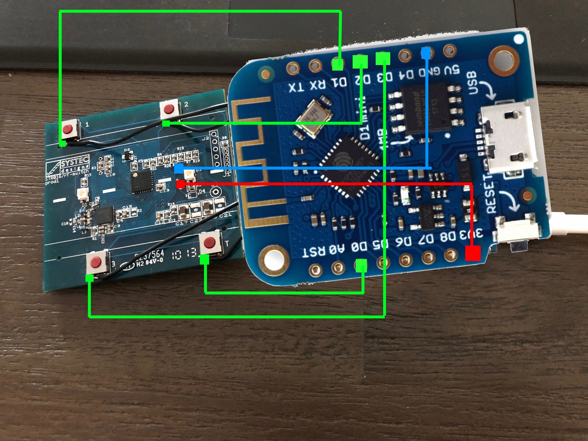
Here is the endresult:

I have build a simple bit of code to automate it and a simple web app to support it.
any request will respond with the simple webinterface
The following URL’s can be called from any device to controll the ventilation system:
Webinterface:
http://[IP Address]/
Mode 1:
http://[IP Address]/mode1
Mode 2:
http://[IP Address]/mode2
Mode 3:
http://[IP Address]/mode3
Mode Time:
http://[IP Address]/modeT
Mode Time x2:
http://[IP Address]/modeT2
Pairing:
http://[IP Address]/pairing
Webinterface:

Source Code:
Change your WiFi SSID and Password to make it work.
#include <ESP8266WiFi.h>
#include <WiFiClient.h>
#include <ESP8266WebServer.h>
#include <ESP8266mDNS.h>

#ifndef STASSID
#define STASSID "MY SSID"
#define STAPSK  "MY PASSWORD"
#endif

const char* ssid = STASSID;
const char* password = STAPSK;

ESP8266WebServer server(80);

void httpDefaultResponce() {
  digitalWrite(D4, 0);
  server.send(200, "text/html", "<html><head></head><body><b>Control</b><br><a href=\"/mode1\">Set Mode: 1</a><br><a href=\"/mode2\">Set Mode: 2</a><br><a href=\"/mode3\">Set Mode: 3</a><br><a href=\"/modeT\">Set Mode: 4 15 Minutes</a><br><a href=\"/modeT2\">Set Mode: 4 30 Minutes</a><br><br><br><b>Pairing<b><br>The ventilation motor allows pairing only in the first 10 minutes after getting power.<br>To pair a remote, disconnect the power cable and then reconnect the power cable of the ventilation motor.<br><a href=\"/pairing\">Start pairing.</a></body></html>");
  digitalWrite(D4, 1);
}

void cleanStates() {
  digitalWrite(D0, 0);
  digitalWrite(D1, 0);
  digitalWrite(D2, 0);
  digitalWrite(D3, 0);
}

void setup(void) {
  pinMode(D0, OUTPUT);
  digitalWrite(D0, 0);
  pinMode(D1, OUTPUT);
  digitalWrite(D1, 0);
  pinMode(D2, OUTPUT);
  digitalWrite(D2, 0);
  pinMode(D3, OUTPUT);
  digitalWrite(D3, 0);
  pinMode(D4, OUTPUT);
  digitalWrite(D4, 1);
  Serial.begin(115200);
  WiFi.mode(WIFI_STA);
  WiFi.begin(ssid, password);
  Serial.println("");

  // Wait for connection
  while (WiFi.status() != WL_CONNECTED) {
    delay(500);
    Serial.print(".");
  }
  Serial.println("");
  Serial.print("Connected to ");
  Serial.println(ssid);
  Serial.print("IP address: ");
  Serial.println(WiFi.localIP());
  digitalWrite(D1, 1);
  if (MDNS.begin("esp8266")) {
    Serial.println("MDNS responder started");
  }

  server.on("/", httpDefaultResponce);

  server.on("/mode1", []() {
    httpDefaultResponce();
    digitalWrite(D1, 1);
    delay(200);
    cleanStates();
  });

  server.on("/mode2", []() {
    httpDefaultResponce();
    digitalWrite(D2, 1);
    delay(200);
    cleanStates();
  });

  server.on("/mode3", []() {
    httpDefaultResponce();
    digitalWrite(D3, 1);
    delay(200);
    cleanStates();
  });

  server.on("/modeT", []() {
    httpDefaultResponce();
    digitalWrite(D0, 1);
    delay(200);
    cleanStates();
  });

  server.on("/modeT2", []() {
    httpDefaultResponce();
    digitalWrite(D0, 1);
    delay(2500);
    cleanStates();
  });

  server.on("/pairing", []() {
    httpDefaultResponce();
    digitalWrite(D0, 1);
    digitalWrite(D1, 1);
    delay(7000);
    cleanStates();
  });

  server.onNotFound(httpDefaultResponce);

  server.begin();
  Serial.println("HTTP server started");
}

void loop(void) {
  server.handleClient();
  MDNS.update();
}
